Extrude
The Extrude tool is available for places that have been drawn in 2D, 3D or 360 mode (circle, rectangle and polygon only). The extrusion can be applied in both above and below a place.
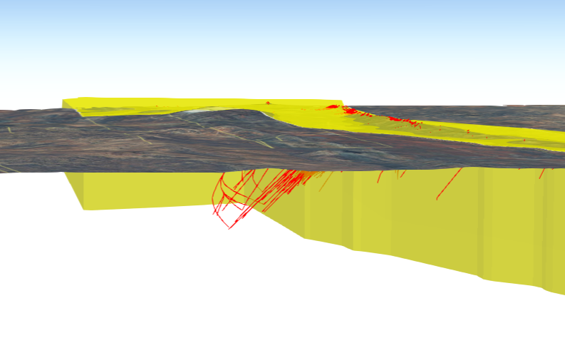
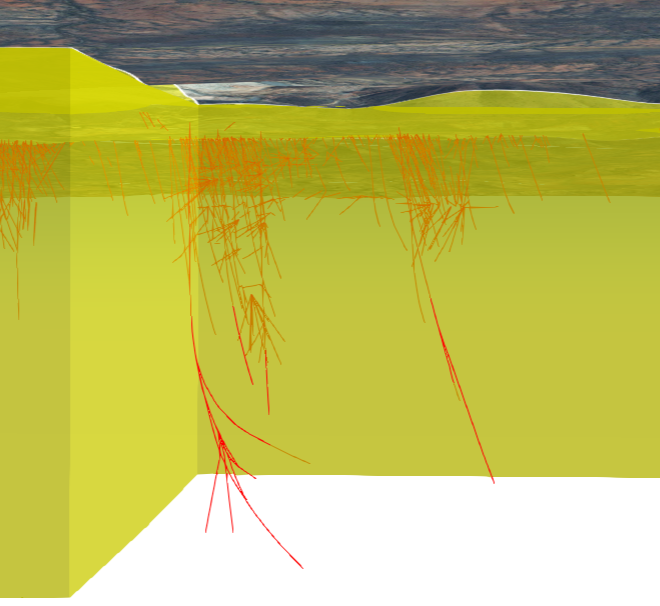
Any extrusions that extend below the ground surface can be viewed in 360 mode.
The extrude tool is also available for polygon places that have been added via the search tools (e.g. Lot on plan) or by using the identify tool on an added layer (e.g. Land parcel), where a polygon is returned.
To replicate this example:
- Add the Land parcel and Brisbane buildings layers to your map.
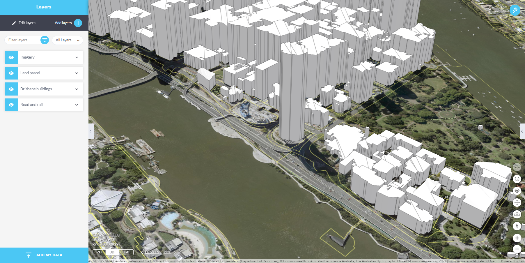
- Expand the toolbar and select the identify tool. Identify a parcel of interest and add it as a place.
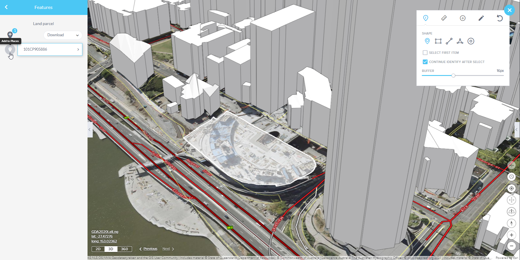
- Open the places panel, expand the place to change the symbology and select Extrude.
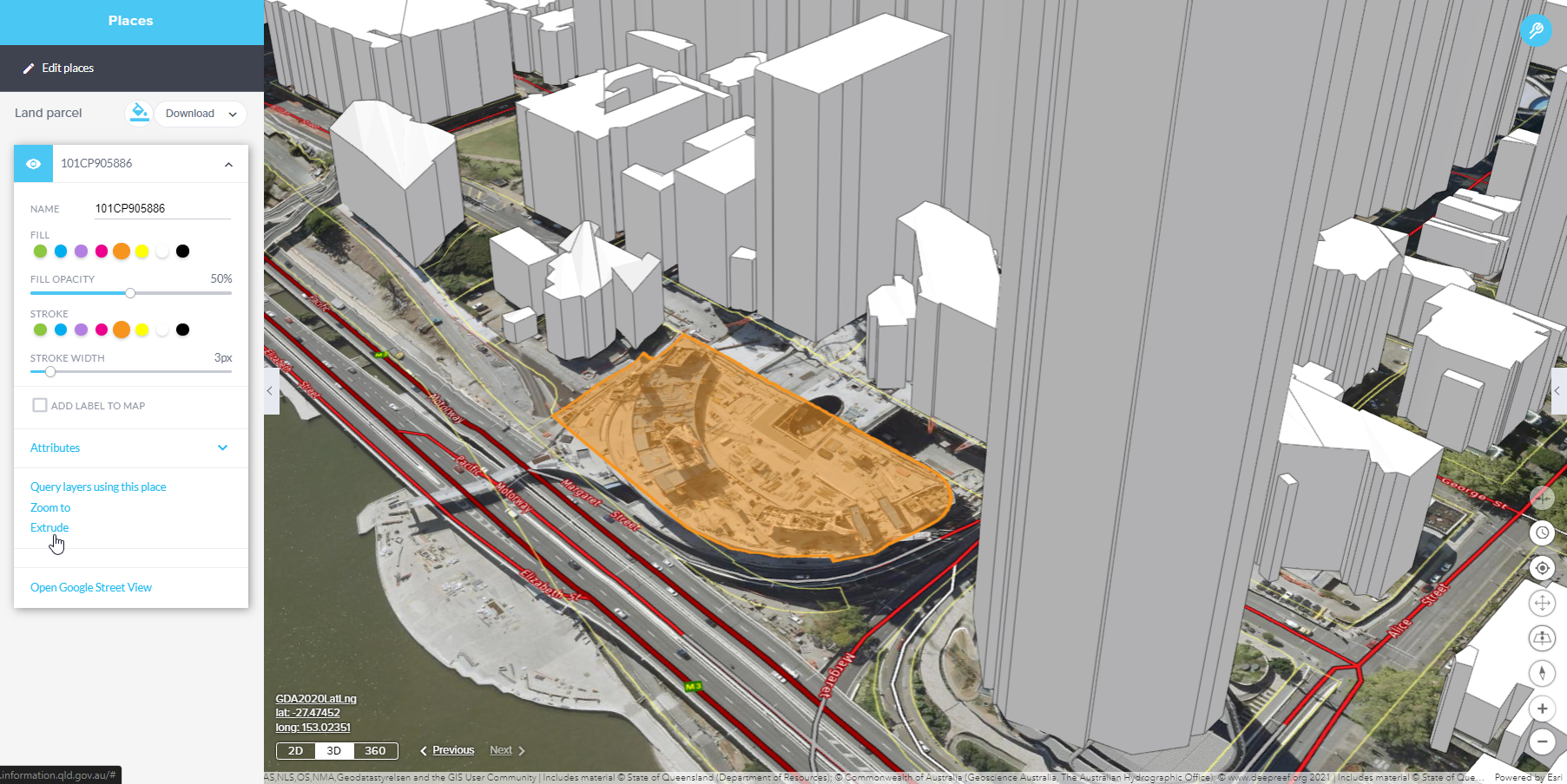
- The extrusion height settings can be adjusted to suit.
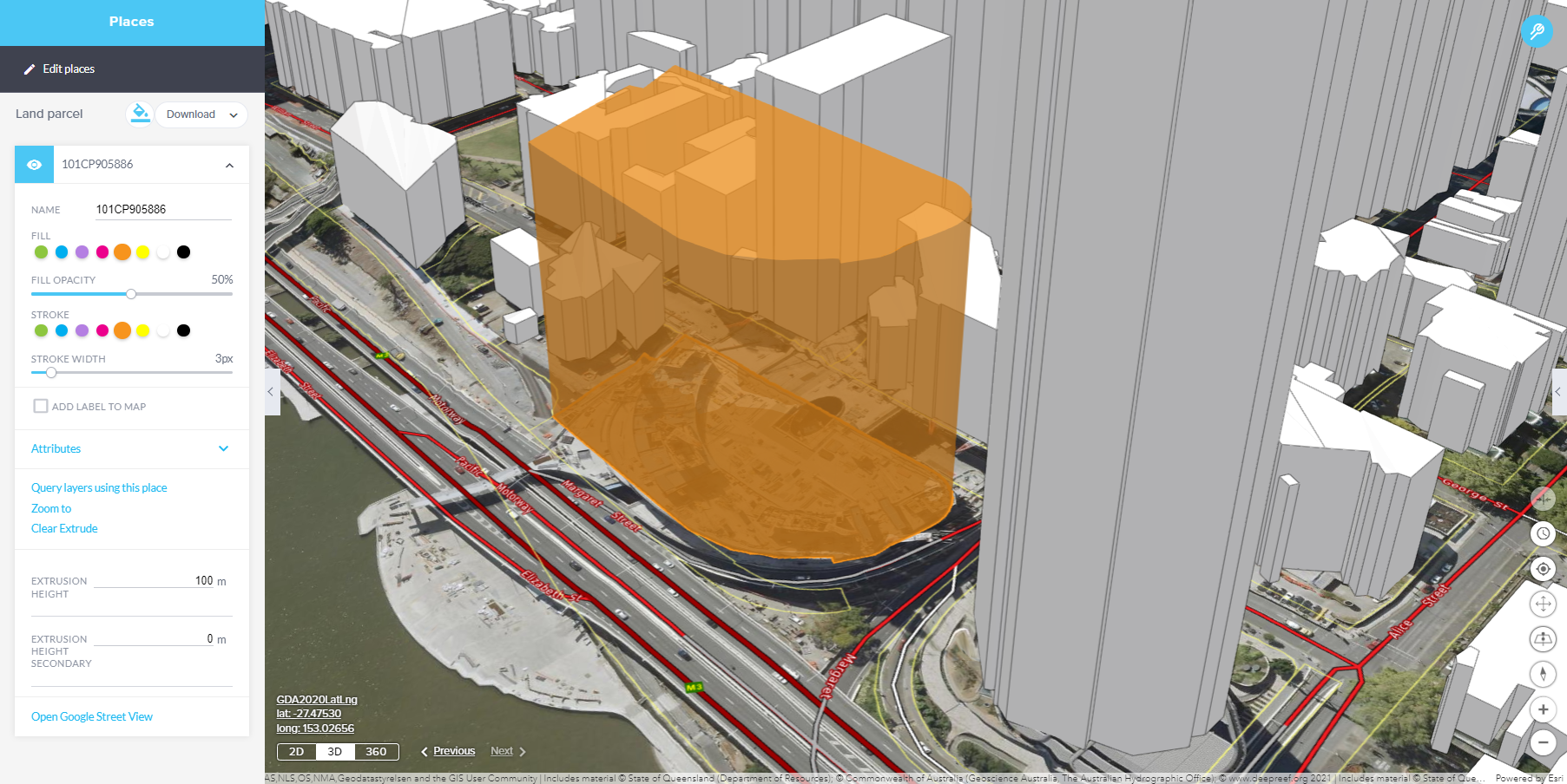
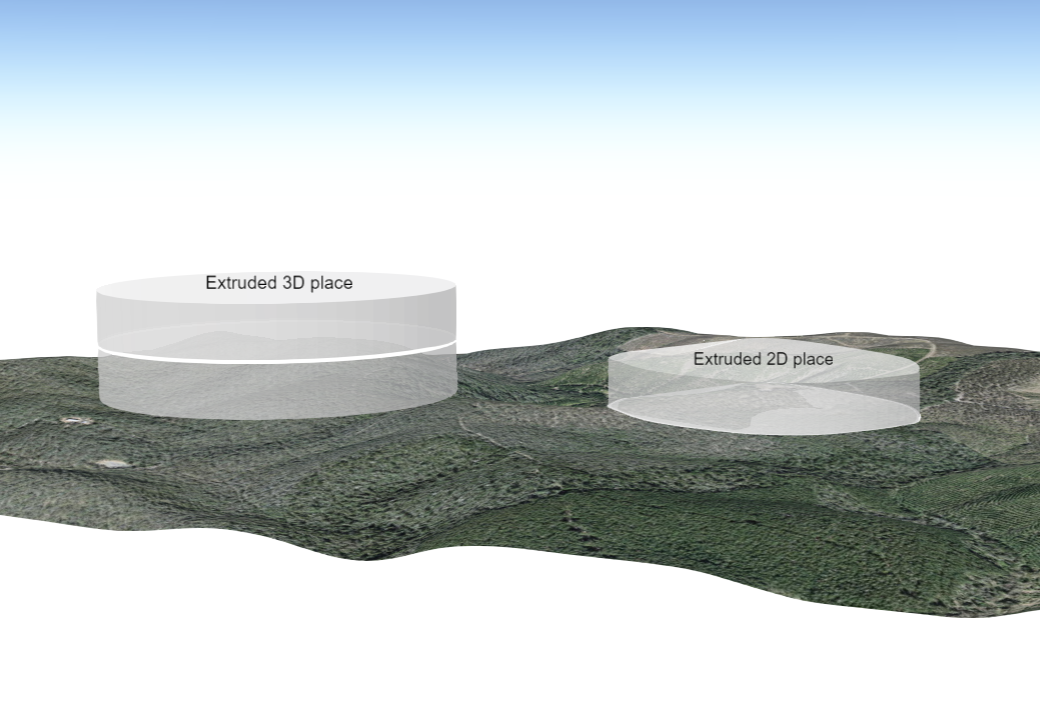
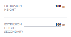
By default the extrusion height is set as 100m above and below the place. These values can be specified by the user.
The extrusion displayed takes into account the height of the vertices of the place.
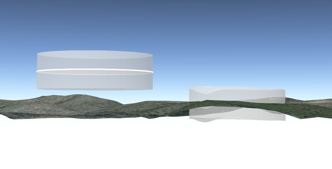
If the extrusion extends below the surface of the earth, switch to 360 mode to view the extrusion above and below the ground.
The opacity setting applied to the fill of a place also affects the extrusion associated with it.
In 3D and 360 modes, where 2D places are draped over the terrain, the extrusion displayed extends from each of the vertices.
It's important to note that the extrude tool is not supported for point, line, or text places. Therefore, you cannot use the extrude tool to create extrusions for these types of place features.
Additionally, if you've added a label to a place, it will appear above the extrusion in the 3D or 360 view, ensuring that both the label and extrusion are visible to users. This arrangement helps provide context and information to viewers when working with 3D or 360 representations of geographic data.
The following outlines the behaviour of extruding polylines in the GeoResGlobe
Extruding Polylines Added in 3D Mode
- When a polyline has been added in 3D mode, applying an extrusion will typically result in the extrusion being applied to the entire 3D place.
- This behaviour is suitable for representing three-dimensional objects that are meant to maintain their elevation variations along the length of the polyline, such as buildings or retaining walls.
Extruding Polylines Added in 2D Mode
- In situations where you want to extrude a polyline to depict features like a fence on a slope, it's advisable to first revert the polyline to 2D mode before applying the extrusion.
- Reverting to 2D mode likely flattens the polyline and ensures that the extrusion is applied in a way that does not consider the elevation variations of the original 3D mode.
This differentiation is important for accurately representing the intended features in your map. It allows you to have control over whether elevation information is preserved during the extrusion process or whether the extrusion is applied in a flat 2D manner. It's particularly useful for scenarios where you need to depict features like fences, which typically follow the contour of the land rather than being elevated.
When extruding a polyline, users can adjust the height and width of the extrusion. By default, the extrusion height for polylines is set to 30m, and the width is set to 5m.
If these values have been adjusted and the extrusion cleared, if the user chooses to re-instate the extrusion the application will remember the previously edited values for that place within the current session.
Variations in the extrusion result can occur with the following scenarios
- 3D lines added to a group that has the elevation mode of ‘On the Ground’.
- 3D lines drawn using the drawing tools in 3D mode, then ‘Revert to 2D place’.
- 2D lines viewed in 3D mode.